What Did FTG-11 Actually Prove? (April 4, 2019)

On March 25, 2019 the U.S. Missile Defense Agency (MDA) conducted FTG-11, a salvo test of the US Ground-based Midcourse Defense (GMD) system in which two interceptors were fired, just under a minute apart, at a single ICBN-range missile.  

In a press release later that day, MDA described the test as follows:

“This test was the first salvo engagement of a threat-representative ICBM target by two Ground Based Interceptors (GBI), which were designated GBI-Lead, and GBI-Trail for the test. The GBI-Lead destroyed the reentry vehicle, as it was designed to do. The GBI-Trail then looked at the resulting debris and remaining objects, and, not finding any other reentry vehicles, selected the next ‘most lethal object’ it could identify, and struck that, precisely as it was designed to do.”

The MDA press release stated that “Initial indications show the test met requirements.”  It also quoted MDA Director Air Force Lt. General Samuel A. Greaves:

“The system worked exactly as it was designed to do, and the results of this test provide evidence of the practicable use of the salvo doctrine within missile defense. The Ground-based Midcourse Defense system is vitally important to the defense of our homeland, and this test demonstrates that we have a capable, credible deterrent against a very real threat.”

At yesterday’s (April 3, 2019) hearing on missile defense before the Strategic Forces Subcommittee of the Senate Armed Services Committee, General Greaves reaffirmed the success of the test.  Asked by Senator Angus King whether the test was a success, General Greaves stated that although there were nine months of data to review, the “initial look says it was a complete success.”

Senator King then asked him to “Define complete success, did the bullet hit the bullet?”

After giving some background information on testing, General Greaves stated:

“But this test was different because we launched within a very short period of time two Ground-Based Interceptors operationally released by the combatant commander using their operational processes –which is very important — and the lead interceptor intercepted the ICBM-representative threat.  But what’s most important is that it created a debris field — and this test has been 10 years or more in the making — and the importance of that was the trailing — the second — interceptor was able to discern the debris from the next most lethal object — I can talk about it in a classified forum — and also intercepted that object. What that means is [an] enemy concept of operations which seeks to confuse our missile defense system by launching junk or debris would not be successful, that’s why it was a success.” [My transcription from the video of the hearing.]

 Both the press release and the General Greaves quote immediately above make it clear that after the first intercept, there remained both debris and at least one other object.  All of these other objects must have had an appearance sufficiently different from the warhead so that the first interceptor could select the warhead.  And at least one of these other objects must have had an appearance sufficiently different from the debris so that the second interceptor could identify it.

So although when Senator Dan Sullivan asked General Greaves if the second interceptor had hit the largest debris fragment, General Greaves replied “Yes, sir,” he immediately clarified this saying that it hit “the next most lethal object” which he defined as ‘the next object that most closely resembles a threat vehicle.”

But what did FTG-15 actually prove?  Did it provide “evidence of the practicable use of the salvo doctrine” as the press release claimed?  Did it demonstrate that such the salvo doctrine would defeat enemy attempts to confuse the system as General Greaves quote suggests? I think it is clear the answer to both questions is “No.”

Strictly speaking, the test did demonstrate that the GMD system could intercept a target resembling a warhead against a field of debris, none of which resembles a warhead.  But why would any enemy try to defeat the system with such an obviously ineffective tactic (unless the warhead was disguised to look like debris)?  Moreover, the debris field that an attacker might deploy along with its warhead likely would look quite different than the debris field produced by an interceptor hitting a warhead or other object.  Finally, there was no need to launch two interceptors to conduct this demonstration.  Debris could have been launched along with the first warhead, and there would have been no need to waste a second $70 million GBI interceptor.

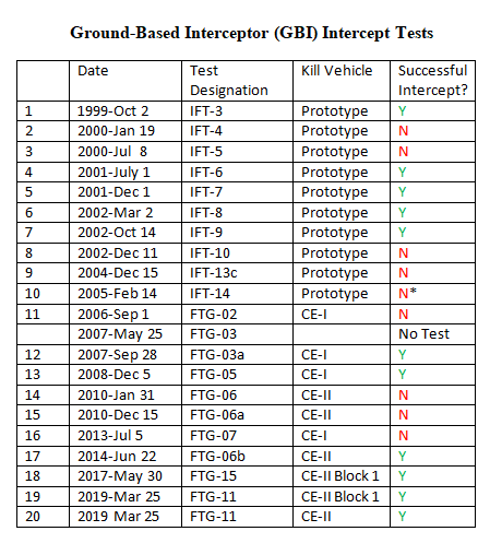
More importantly, the fundamental purpose of the salvo firing doctrine is to compensate for low missile defense system reliability, the interceptor reliability in particular.  For example, if the GBIs were believed to be 60% reliable (although this is slightly higher than its success rate in intercept tests – see table at end of this post — there is not enough test data to know their what actual reliability is), then salvo firing N interceptors gives a probability of killing the target of PKN = 1 – (1-0.6)N.   So for one interceptor PK1 = 0.6, for a two-interceptor salvo PK2 = 0.86, and for a three interceptor salvo PK3 = 0.936.  This is why many observers of the GMD system have speculated that the GMD firing doctrine is at least a three or four interceptor salvo against a single attacking missile.  This assumes that the failure of any one interceptor is statistically independent of the others.

A two interceptor salvo firing doctrine benefits the defense against an attacking missile when the first interceptor fails.  There is no benefit from the second interceptor if the first interceptor destroys the target, as was the case in FTG-11. 

More importantly, when an attacker takes deliberate and effective steps to defeat the defense (countermeasures), the salvo doctrine will be much less effective.  This is because if a countermeasure (and not an interceptor reliability problem) causes the first interceptor to fail, then there is a substantial probability that the countermeasure will also cause subsequent interceptors to fail.  For example, consider a case in which the warhead is disguised to look like a decoy and is accompanied by five credible light-weight decoys.  If the interceptor is unable to distinguish between the disguised warhead and the decoys, it will have to choose one of six potential targets.  Assuming  the interceptor has a same reliability as assumed above, 0.6, the chance of a successful intercept of the warhead with a single interceptor  is only PK1 = 0.6 * (1/6)  = 0.10. In a salvo of two interceptors, if the first interceptor fails to destroy the warhead, the odds for the second one are slightly better, because there is an 60% chance it will see only five targets, so the kill probability for this interceptor is P­K1­ = 0.6*0.6*(1/5) + 0.4*0.6*(1/6) = 0.112, and the overall success rate for the two intercept salvo is only PK2 = 0.201.  The salvo firing doctrine does not solve the countermeasure problem, which has long been recognized as the most important and difficult problem facing an above-the-atmosphere defense such as the GMD system

It is worth noting that FTG-11 was not MDA’s first attempt to intercept a target against a debris field.  On November 1 2015, MDA conducted test FTO-02 event 2.  In this test, a short range ballistic missile target was successfully intercepted by a THAAD interceptor, creating a debris field.  An Aegis SM-3 Block IB TU interceptor then attempted to intercept a medium-range ballistic missile against the background of this debris field.  However, the SM-3 missile failed before it could make the intercept attempt.  The target was then destroyed by a second THAAD interceptor, although it is unclear (to me) if the target was still in the vicinity of the debris field.  However, even prior to FTO-02, MDA had conducted “tests to verify interceptor performance in debris clouds” although these most likely were of systems such as the Aegis SM-3 or THAAD and involved only a single interceptor.

I think FTG-11 is better regarded as two separate intercept tests, albeit separated by less than a minute.  I have accordingly updated my Tables of Intercept Tests post of November 30, 2018, counting both tests as successes.  The GMD table from that post is below:

GMDTestsApril2019

Estimating the Range of the Long Range Discrimination Radar (April 2, 2019)

In my post of February 11 2019, I discuss what is publicly known about the Long-Range Discrimination Radar (LRDR) now under construction in central Alaska and the closely related Homeland Defense Radars (HDRs) to be built in the Pacific. The post also discussed the new SPY-6 radar to be deployed on new construction U.S. Navy Aegis destroyers starting in about 2023 and the Lockheed Martin Solid State Radar (SSR) to be used in the planned Japanese Aegis Ashore missile defense facilities.

In this post, I attempt to make some estimates about the LRDR’s capabilities, and, by extension, those of the HDRs. This requires making some speculative, although I think reasonable, assumptions.

Only a few technical details are known about the LRDR. It has two antenna faces. Artist renderings of the LRDR suggest that the boresites of the two faces are separated by about 120°, which is consistent with the reported requirement that the LRDR must have a “wide instantaneous field of view to enable wide area defense”(see my post of January 30, 2019).  It is known that the LRDR operates in S-Band, which extends from 2 GHz to 4 GHz. S-Band was chosen over X-Band, which offers superior discrimination capabilities, largely due to cost considerations. It likely has an antenna area of about 280-300 m2 per antenna face.  For convenience, I repeat the part of my February 11 2018 post on which this conclusion about the antenna is based:

“A 2017 article stated that the LRDR will have two 3,000 square-foot antenna arrays (3,000 sq-ft = 279 m2).[1]  According to Chandra Marshall, Lockheed’s LRDR program manager, the LRDR will be about 25 times larger than a SPY-1 antenna.[2] Assuming this comparison applies to each face of the radars, since a SPY-1 antenna face has an aperture of about 12 m2, this gives an aperture of about 300 m2 for the LRDR.”

Based on this information, what can we deduce about the LRDR’s capabilities?  First, I’ll assume the smaller of the of the two antenna areas above, A = 280m2.  Assuming a square antenna, as suggested by the renderings in my February 11 post (the drawing in the January 30 post suggests a circular antenna, but this is likely an older rendering), then the antenna would be D = 16.7 m square.  Assuming that the LRDR operates at a wavelength of about λ = 8.6 cm, corresponding to a frequency of about 3.5 GHz (for comparison, the current Aegis SPY-1 radar operates at 3.1-3.5 GHz), gives an approximate beamwidth of θ ≈ λ/D = 16.7/0.086 = 0.0051 rad = 0.29°.  This gives a beamwidth of about 20 km at a range of 4,000 km.  The gain G of the antenna, assuming it is fully populated with T/R modules, is given by G = 4πA/λ2 = 480,000.

To try to get a rough estimate of the LRDR’s tracking range, I start with a basic form of the radar equation:

RadarEq04022019

Rmax = maximum radar range (m),

ρ = antenna aperture efficiency,

Pav = radar average power (W),

A = antenna area (m2),

G = antenna gain,

td = beam dwell time,

σ = radar cross section of target (m2),

k = Boltzmann’s constant (1.38×10⁻²³ J/K),

T0 = 290 K, FN = receiver noise figure,

(S/N) = signal-to noise ratio required for detection,

LS = system losses.

The problem here is that we do not know the value of many of the quantities in the radar equation, most notably Pav. One possible way around this problem is to compare the LRDR to another radar using similar technology but for which more information is available. The obvious choice here is the Aegis SPY-6.

Both the LRDR and the SPY-6 are active array radars using GaN Transmit/Receive (T/R) modules and both operate in S-Band. Both radars are state-of-the-art in their use of new GaN technology. Raytheon (the maker of the SPY-6) competed with Lockheed Martin for the LRDR, HDR-H and the Japanese Aegis Ashore SSR and won each of these contracts. This suggests that the radar technology used in the LRDR is at least comparable with that used in the SPY-6. So I will assume both radars operate at the same frequency (wavelength), will take ρ/FNLS to be the same for both radars and assume that the T/R modules in each radar have the same average power.

Since both radars operate in S-Band, it is reasonable to assume that the target radar cross section will be the same for both radars. If we then operate both radars using the same dwell time and require the same S/N for tracking, we get:

L4/R64 ≈ PLALGL/P6A6G6,

where the subscript “L” denotes the LRDR and the subscript “6” denotes the SPY-6, and the P is average power. If both radars have the same spacing between modules[3], then the average power per antenna face will be proportional to the antenna area, and since G = 4πA/λ2, we get:

L4/R64 = AL3/A63.

Using 280 m2 for the LRDR antenna area and taking the antenna area for one face of the SPY-6 to be 13.8 m2 (as discussed in my February 11 post), we get:

RL4/R64 ≈ AL3/A63 = 2803/13.83 = 20.33 = 8,370 and RL ≈ 9.6R6.

Thus if the LRDR and SPY-6 were operated in the same way and against the same target, the detection and tracking ranges for the LRDR will be about 9.6 times that of the SPY-6.  In actual practice, the LRDR will likely be operated in a way that will give an even greater range advantage.

However, this still does not give us a numerical range for the LRDR because we don’t know the range of the SPY-6.  However, we do know that the SPY-6 is expected to be at least 15dB ≈ 31.6 times more sensitive than the current Aegis SPY-1radar (see my February 11 2019 post). If the subscript “1” denotes the SPY-1, then we have:

RL4/R14 ≈ 8,370*31.6 = 264,000 and RL ≈ 22.7R1.

My post (along with Theodore Postol) of October 23, 2012 notes the claim that the SPY-1 “can track golf ball-sized targets at ranges in excess of 165 kilometers.”[4]  This claim was not made in the context of ballistic missile defense, but rather for air targets.  A golf ball-size (1.68 inches diameter) metallic sphere corresponds to radar cross section (RCS) of about 0.0025 m2 at 3.3 GHz.  Scaling this to a RCS of 0.03 m2 (for a missile target at S-Band) gives a range in excess of 310 km. Since the Aegis radar must be continually scanning the sky for incoming threats, this range is likely based on a relatively short dwell time.  Using a relatively long dwell time of 0.1 second and S/N = 20 for detection and tracking, we obtained a range of 550 km.  Using these two figures as rough lower and upper bounds on the Aegis radar range, gives upper and lower range estimates for the LRDR of 7,000 to 12,500 km.”

In a missile defense context, such large tracking ranges are not usually obtainable, because at ranges greater than about 4,000 km missile targets on minimum energy trajectories will not rise above the horizon.  However, even using the 7,000 km lower-bound range figure, the LRDR would be able to obtain a S/N on a 0.03 m2 target of nearly 200 at a range of 4,000 km.  Obviously, at shorter ranges the S/N would be much greater.

A high S/N ratio can also be essential for constructing a target object map (TOM) that allows a scene (threat cloud) viewed by a radar to be translated into the scene that would be seen by an infrared-homing kill vehicle.  For a brief discussion of this issue, see Countermeasures, pp. 77-79.[5]

As described by the 2012 National Academy of Sciences report:

“With adequate signal-to-noise ratio, a monopulse tracking radar can limit measurement error to less than 1 percent of its beamwidth. Over extended track periods, the relative positions can be refined by a further order of magnitude.  Along with measurement of relative range to a fraction of a meter, using wideband waveforms, these position data provide a three-dimensional target object map that can be converted to the angular coordinates of a homing seeker, ensuring proper registration of each object in the target cluster.”[6]

However, measuring an angular position to 1 percent of a beamwidth with a monopulse radar requires a very large S/N ratio. For a square antenna with sides D, the angular measurement error is given by:[7]

Δθ = 0.5 (S/N)-0.5 (λ/D)

Since λ/D is the approximate beamwidth, achieving an angular measurement of 1 percent of the beamwidth requires S/N ≈ 2,500.

For the lower-bound and upper-bound estimates above, a S/N of 2,500 would be achieved at ranges of about 2,100 and 3,700 km respectively.

What does the above say about the Homeland Defense Radars (HDRs)?  These are often described as scaled-down versions of the LRDR.  For example, the HDR-H, to be built in Hawaii, fills a role previously proposed for a radar that was to be called the Medium Range Discrimination Radar.  However, the projected costs of the HDRs strongly suggest that they are not much smaller than the LRDR. As discussed in my post of February 11, the HDR-H is expected to cost about $1.0 billion, about 77% of $1.3 billion cost of the LRDR.  However, the LRDR will have two radar faces, while the HDR-H will have only one.  This factor alone could account for the cost difference.

The HDR-P, on the other hand, will have two radar faces and is projected to cost the same $1.3 billion as the LRDR.  It thus seems likely to be similar in scale to the LRDR.  As discussed in my post of February 11, although the United States has not announced where the HDR+P will be built, Japanese media reports indicate that it will be built in Japan.  A two-faced HDR built in northern Japan would be able to look deep into both China and eastern Russia, and would undoubtedly encounter strong opposition from both countries.

A December 2018 Government Accountability Office report stated that: “According to DOD officials, the department may no longer need Cobra Dane to meet the ballistic missile defense mission after MDA fields a new radar in the Pacific region in fiscal year 2025,” but that it would continue to operate Cobra Dane until it was replaced with a system with greater or equal capabilities.[8] (The date for the Pacific radar has since slipped to 2026.)  The same report also stated that there would be no radar tracking coverage gap (between the TPY-2s in Japan, the Cobra Dane on Shemya Island, and the LRDR in central Alaska) once the LRDR was deployed for North Korean missiles fired towards the continental United States.  However, since the Cobra Dane is not capable of discrimination, there would be a discrimination gap for North Korean missiles launched towards the eastern United States.  In addition, once the Cobra Dane is retired (current plans call for operating it until at least 2030) there would be a tracking gap as well.

The deployment of a two-faced HDR-P in either Japan or Shemya would close both of these gaps.

—————————————————————————-

[1] Marcus Weisgerber, “Pentagon Eyes Missile-Defense Sensors in Space,” Defense One, August 30, 2016.

[2] David B. Larter, “Here’s the Latest on Lockheed’s Massive Long-Range Anti-Ballistic Missile Radar,” Space News, December 9, 2019.

[3] Since the Aegis radar may only need to scan 90 degrees with each radar face, its spacing between modules could be greater than for the LRDR.  This would give a result even more favorable to the LRDR.

[4] John A. Robinson, “Force Protection from the Sea: Employing the SPY-1D Radar,” Field Artillery, March-June 2004, pp. 24-25.

[5] A.M. Sessler, J.M. Cornwall, B. Dietz, S. Fetter, S. Frankel, R. L. Garwin, K. Gottfried, L. Gronlund, G. N. Lewis, T. A. Postol, and D. C. Wright, Countermeasures: A Technical Evaluation of the Operational Effectiveness of the Planned US National Missile Defense System, Cambridge, Massachusetts: Union of Concerned Scientists /MIT Security Studies Program, 2000. Online at: http://www.ucsusa.org/sites/default/files/legacy/assets/documents/nwgs/cm_all.pdf.

[6] U.S. National Academy of Sciences, National Research Council, Committee on Assessment of Concepts and Systems for U.S. Boost-Phase Missile Defense in Comparison to Other Alternatives, Making Sense of Ballistic Missile Defense: An Assessment of Concepts and Systems for U.S. Boost-Phase Missile Defense in Comparison to Other Alternatives, Washington, D.C.: The National Academies Press, September 2012, p. 137.  Online at: http://www.nap.edu/catalog.php?record_id=13189.

[7] J.C. Toomay, Radar Principles for the Non-Specialist, 2nd ed., Mendham, New Jersey: Scitech Publishing, 1998, pp. 56-58

[8] Government Accountability Office, “Missile Defense: Air Force Report to Congress Included Information on the Capabilities, Operational Availability and Funding Plan for Cobra Dane,” GAO-19-68, December 2018, pp. 2, 11. Online at: https://www.gao.gov/assets/700/696076.pdf.